Very good information provided by Steve here, and to add just a little to the discussion...
Most extractor deflection issues I've seen recently have been of too much deflection rather than too little...which cause failures to go to or return to battery. I've seen as much as .050 inch in a few, but run to .035-.040 inch on average. As our favorite small town sheriff would say. "That's way yonder too much."
And too often the cure has been that heavy bevel on the bottom of the tensioning wall in the attempt to create a camming surface that lets the case rim open the extractor up gradually instead of having it literally hit a wall...but when that bevel is taken just a little too far, it brings on other problems.
Excessive extractor deflection and failures to go to battery has also probably resulted in more people reaching for the Dremel, often ruining feed ramps than any other single cause. Whenever I see one of Dremel Dan's killer-diller double throwdown ramp'n'throat jobs...excessive extractor deflection is there almost without fail.
When excessive deflection is part of the picture, it can come from one of three places. Either the channel is oversized...drilled on an angle...or the front pad of the extractor is undersized. To compound the channel problem...very often when it's drilled on an angle...the rear of the extractor is too far to the right for the firing pin stop to limit its rotation. When that's in play, there are only two cures. Either weld up the FP stop's slot in the extractor and fit...or get a new slide.
At the other end, you can weld up the front pad and refit, or you can use a safe-side rail file to remove material from the tensioning wall to bet the proper deflection...which also requires shortening the claw from tip to wall to keep it from bottoming out in the extractor groove. I like to see .035-.036 inch for this dimension.
Which brings us to the case itself.
In the past, I've noticed two issues with the Russian .45 Auto cases.
The first is that they're a little on the small side, averaging around .470 inch...with several running as small as .465 or so.
The other one is more serious.
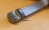
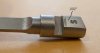
The extractor grooves are too short and the angle forward too abrupt, as shown below. Apparently the Russians copied the original .45 Auto extractor groove geometry circa 1905 instead of the revamped dimensions that came later.
This groove geometry is what led many people to believe that the steel cases not releasing their grip on the chamber wall was responsible for breaking their extractors...but this is the real culprit.
It's interesting to note that, during WW2, the steel-cased ammunition meant for submachine guns had the same groove geometry...which worked well with the extractors in Thompson and M3 "Grease" guns...but not with those in .45 pistols. So, take note.
The WW2-era steel-cased ammunition is still seen at gun shows once in a while. That stuff and the Russian ammunition will break an extractor when the case is slammed backward against the breechface, and the abrupt angle slams into the nose of the extractor.


") My apologies for the delays, I get about one day a week to go to the range so it has been agony in quick turn-around. I attempted to flatten the original extractor surfaces and while ejection was a tiny bit better, there were a couple that still went to the forehead and those cases that got me are manged like the prior. No signs of the brass hitting the port this time.
My apologies for the delays, I get about one day a week to go to the range so it has been agony in quick turn-around. I attempted to flatten the original extractor surfaces and while ejection was a tiny bit better, there were a couple that still went to the forehead and those cases that got me are manged like the prior. No signs of the brass hitting the port this time.