S&W model 10 disassembly,inspection,select repairs and reassembly - discussion

Status
Not open for further replies.
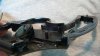
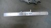
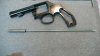
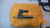
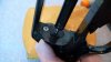
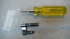
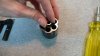
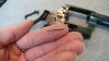
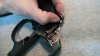
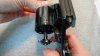
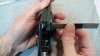
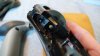
Carefully filed a raised edge by the damaged area and blended it as best as I could.:
attachment.php


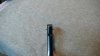
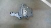
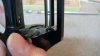
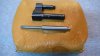
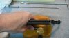
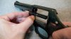
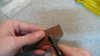
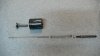
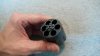
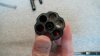
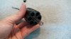
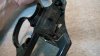
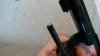
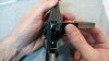
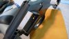
Inspecting the firing pin bore, pivot bore and hand slot for burrs. Looks good.:
attachment.php


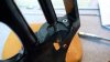
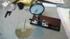
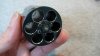
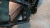
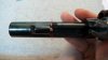
Cylinder stop slot looks good too.:
attachment.php


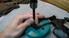
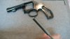
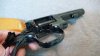
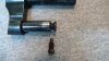
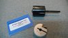
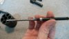
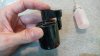
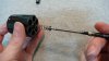
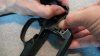
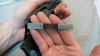
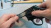
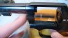
Put the yoke into the frame (without yoke screw). It swings smoothly, so nothing needed here.:
attachment.php


.
 

Attachments

  • m10c-45.JPG
    m10c-45.JPG
    47.4 KB · Views: 2,411
  • m10c-46.JPG
    m10c-46.JPG
    47 KB · Views: 2,405
  • m10c-47.JPG
    m10c-47.JPG
    57.7 KB · Views: 2,405
  • m10c-48.JPG
    m10c-48.JPG
    53.8 KB · Views: 2,407
Last edited:
The portion of the frame where the rebound slide, um, slides. If I had a stone I might try and clean the surface up a little bit, but it's ok. The contact marks indicate even contact with the rebound slide.:
attachment.php


The roll pin that locates the grips is sticking out a little more on the right than the left :p:
attachment.php


Brownells 1/8" roll pin punch (has a little pilot that fits into the roll pin) and a couple light taps sets things aright.:
attachment.php


Checking the hammer block for trueness.:
attachment.php


.
 

Attachments

  • m10c-49.JPG
    m10c-49.JPG
    68.8 KB · Views: 2,405
  • m10c-50.JPG
    m10c-50.JPG
    60.4 KB · Views: 2,385
  • m10c-51.JPG
    m10c-51.JPG
    60.9 KB · Views: 2,386
  • m10c-52.JPG
    m10c-52.JPG
    105.2 KB · Views: 2,394
Last edited:
Checking the hammer block for trueness part 2. It's good to go.:
attachment.php


Cleaned and Inspected the sideplate. The hammer block moves smoothly and sets slightly below flush in the guideway. All good.:
attachment.php


.
 

Attachments

  • m10c-53.JPG
    m10c-53.JPG
    100.3 KB · Views: 2,388
  • m10c-54.JPG
    m10c-54.JPG
    108.6 KB · Views: 2,385
Last edited:
I don't have a Smith and Wesson. I can't wait for your next lesson. This is gunkrankism of the worst sort.
 
Clean & Inspect Barrel & Yoke :

Lewis Lead Remover Kit.:
attachment.php


I forgot to mention; inspect the thin area of frame underneath the barrel threads for any cracks. Preparing to clean the forcing cone with the Lewis Kit.:
attachment.php


Brownells 080-617-038 Range Rod Combo (Service). Used for testing barrel & barrel/cylinder alignment.:
attachment.php


Close up of the range rod head. Service and Match sized heads available. The heads thread onto the rod. Since this is a factory barrel I'm just using the service size.:
attachment.php


.
 

Attachments

  • m10c-55.JPG
    m10c-55.JPG
    78.2 KB · Views: 2,260
  • m10c-56.JPG
    m10c-56.JPG
    74.9 KB · Views: 2,258
  • m10c-57.JPG
    m10c-57.JPG
    82.7 KB · Views: 2,254
  • m10c-58.JPG
    m10c-58.JPG
    47.3 KB · Views: 2,249
Last edited:
Testing barrel alignment with the range rod. It's good. (Later I'll use this tool to check the cylinder alignment).:
attachment.php


Brownells 080-616-002 Crane (yoke) Alignment Tool.:
attachment.php


Very tight fit! I had to clean inside the yoke barrel very thoroughly, lightly lubricate and tap the alignment tool in (and out) with the brass/plastic hammer.:
attachment.php


Yoke and yoke screw in place for alignment test.:
attachment.php


.
 

Attachments

  • m10c-59.JPG
    m10c-59.JPG
    40.9 KB · Views: 2,241
  • m10c-60.JPG
    m10c-60.JPG
    70.6 KB · Views: 2,233
  • m10c-61.JPG
    m10c-61.JPG
    68.2 KB · Views: 2,245
  • m10c-62.JPG
    m10c-62.JPG
    65.9 KB · Views: 2,231
Last edited:
Hard to see, but the alignment gauge is showing that it is ever so slightly off to the 9 o'clock position (as viewed from the front). If this were over the same amount in the 3 o'clock position, it would be acceptable.:
attachment.php


A couple smacks with the plastic side of the hammer with the yoke in the fully extended position and alignment tool in place.:
attachment.php


Exactly centered! Note: For up/down adjustments, there is a simple tool shaped like a wedge. For left/right adjustments, any non-marring hammer can be used.:
attachment.php


Yoke function & endshake check. The 'Yoke Barrel Flange' is in acceptable contact with the frame and no yoke endshake detected. For yoke endshake correction, please see the Kunhausen book and the thread by THR member, machinisttx, http://www.ar15.com/forums/topic.html?b=5&f=18&t=63290 .:
attachment.php


.
 

Attachments

  • m10c-63.JPG
    m10c-63.JPG
    47.4 KB · Views: 2,227
  • m10c-64.JPG
    m10c-64.JPG
    60 KB · Views: 2,225
  • m10c-65.JPG
    m10c-65.JPG
    45.5 KB · Views: 2,227
  • m10c-66.JPG
    m10c-66.JPG
    61.6 KB · Views: 2,222
Last edited:
Here's the yoke terminology.:
attachment.php


Close up of the 10-14 yoke and yoke screw assembly. I believe S&W went from the older style, solid yoke screw to the yoke screw 'assembly' for models 10-9 and thereafter. The assembly has a pointed pilot that rides on a spring within the screw. If yoke endshake developes in these later models, I'd guess (but I'm not sure) that it could be corrected in much the same way as the older ones, with the exception of using a larger yoke screw, as it seems no oversized yoke screw assembly currently exists.:
attachment.php
 

Attachments

  • m10c-67.JPG
    m10c-67.JPG
    18.3 KB · Views: 2,205
  • m10c-68.JPG
    m10c-68.JPG
    95.2 KB · Views: 2,215
Last edited:
More to follow in a few days!
:
Truing the yoke face, disassembly & inspection of the cylinder parts, cylinder endshake check, cylinder endshake bearing installation, ..

:)

Any input and critique is definitely welcome. I'm no editor, photographer or gunsmith, so if you have advice or see anything to improve or edit, please let me know. Thanks!

:)

.
 
Last edited:
This is without a doubt one of the best threads I've ever seen - thank you.

I was just getting ready to do some action work on my 63 and the info & photos are invaluable...
 
Sylvan-Forge:

I also think this is one of the coolest threads I've seen! You say you are neither a gunsmith or a photographer...I'm sure most of here vehemently disagree on both counts! Fantastic photos - and the red highlights really make the info pop out.

I love Smith revolvers and I'm fascinated by all the detail. but like many others here, I won't be trying this at home any time soon.

I look forward to the next installments.
 
Wow, continued awesome instruction!! bows.gif bows.gif

Looks like the "pinned" thread is ready to have another step added to it! ;) Hope the mods continue to accomodate you, and update the pinned thread as needed.. It would be a shame to let ANY of these lessons slip off the main page and into the archives.. :)
 
NGIB, thank you for the kind words. If there's anything I can do to help, let me know.

rainbowbob, aww shucks, thanks!

Big Mike, your most welcome!

Mickstix, hehe! Thanks!
Mr. Williams told me to let him know when the thread is finished up and he'll update the sticky.

---

Just want to send props out to Jerry Kuhnhausen. If it weren't for his book, I doubt I'd have been able to do this.

.
 
True Yoke Barrel Face :

Brownells 713-030-000 Yoke Facing Reamer & 713-100-002 Cylinder Endshake Bearings, 0.002".:
attachment.php


After a couple twists with the facing tool (using lube), I deburred the edge with 600 grit E-Z Flex.:
attachment.php


All trued up.
Trimming the yoke barrel face creates cylinder endshake, so now I need to install cylinder endshake bearings inside the cylinder.:
attachment.php


Disassemble & Inspect Cylinder & Extractor Assemblies :
Found this extractor rod tool at gunsmithing-tools.com . Brownells carries one that fits multiple revolver models.:
attachment.php


.
 

Attachments

  • m10c-69.JPG
    m10c-69.JPG
    79.6 KB · Views: 2,181
  • m10c-70.JPG
    m10c-70.JPG
    68.5 KB · Views: 2,169
  • m10c-71.JPG
    m10c-71.JPG
    49.2 KB · Views: 2,161
  • m10c-72.JPG
    m10c-72.JPG
    75.2 KB · Views: 2,171
Last edited:
Prepped the tool by taking it apart and adding a little bit of lube to the washer and pre-tightening it until it would no longer slide onto the extractor rod, then backing it off so it would. Here it's shown mounted as close as possible to the cylinder and 3 fired cases inserted for supporting the extractor star. Modern day S&W extractor rods are left-hand threaded, so "righty loosey".:
attachment.php


Thoroughly cleaned the cylinder & extractor parts.
From the left, starting from the top: Extractor, Cylinder, Center Pin, Center Pin Spring, Extractor Spring, Extractor Rod Collar, Extractor Rod.:
attachment.php


Checking the center pin and extractor rod for straightness. The rod has ~0.002 wobble which I'll have to live with since I don't have any tools precise enough to do the job. (It works fine as is). The center pin rolls smoothly across an old hard-drive disk.:
attachment.php


Reassemble cylinder & extractor assemblies with cylinder endshake bearing :
Assemble the extractor rod + collar and center pin + spring and set it aside.:
attachment.php


.
 

Attachments

  • m10c-73.JPG
    m10c-73.JPG
    78.3 KB · Views: 2,188
  • m10c-74.JPG
    m10c-74.JPG
    75.9 KB · Views: 2,182
  • m10c-76.JPG
    m10c-76.JPG
    74.1 KB · Views: 2,180
  • m10c-77.JPG
    m10c-77.JPG
    51.8 KB · Views: 2,173
Last edited:
Dropping the cylinder endshake bearing into the cylinder.:
attachment.php


A couple drops of lube and seating the bearing with the yoke.:
attachment.php


While the yoke is still in, insert the extractor. Go easy as so you don't beat up the bearing.:
attachment.php


Remove the yoke. Make sure the bearing didn't come with it. Shown is the shaft of the extractor.:
attachment.php


.
 

Attachments

  • m10c-78.JPG
    m10c-78.JPG
    71.3 KB · Views: 2,148
  • m10c-79.JPG
    m10c-79.JPG
    55.1 KB · Views: 2,142
  • m10c-80.JPG
    m10c-80.JPG
    58.5 KB · Views: 2,142
  • m10c-81.JPG
    m10c-81.JPG
    43.5 KB · Views: 2,145
Last edited:
While holding the extractor in with your finger, slide the extractor spring into the cylinder. The spring fits over the extractor shaft. Twist the spring like your screwing it in to ease it's passage.:
attachment.php


Don't forget like me and wonder why everything won't go back together :eek: Left-hand threads!:
attachment.php


Assembled! Extractor star seats flush, does not protrude into the charge holes and has very slight side-to-side and up-and-down play.:
attachment.php


Need to temporarily reinstall the cylinder bolt. Shown is the cylinder bolt plunger and spring.:
attachment.php


.
 

Attachments

  • m10c-82.JPG
    m10c-82.JPG
    53.8 KB · Views: 2,139
  • m10c-83.JPG
    m10c-83.JPG
    63.8 KB · Views: 2,140
  • m10c-84.JPG
    m10c-84.JPG
    45.1 KB · Views: 2,133
  • m10c-85.JPG
    m10c-85.JPG
    45.4 KB · Views: 2,140
Last edited:
With the spring and plunger installed into the cylinder bolt, slide it into the frame, hammer stop end first.:
attachment.php


Push it back far enough to let the pivot clear the frame then press it down and guide the pivot into its bore.:
attachment.php


There it is.:
attachment.php


The pivot is flush.:
attachment.php


.
 

Attachments

  • m10c-86.JPG
    m10c-86.JPG
    80.6 KB · Views: 2,143
  • m10c-87.JPG
    m10c-87.JPG
    65.8 KB · Views: 2,144
  • m10c-88.JPG
    m10c-88.JPG
    67.4 KB · Views: 2,134
  • m10c-89.JPG
    m10c-89.JPG
    65.5 KB · Views: 2,137
Last edited:
Cylinder function check and gauging :
Install the yoke, cylinder and yoke screw. Push the extractor rod a few times to make sure it operates smoothly. Push the cylinder in and out of the frame and check that everything is smooth and locks up proper at the pivot and locking bolt ends and that the cylinder turns smoothly in and out of the frame.:
attachment.php


While testing, I noticed it wouldn't close very smoothly in a small range of the cylinder's rotation. I traced it to the end of the extractor rod where a small portion of the bevel angle was too steep and would hang up on the locking bolt. Had to take everything back down and make up a little turning jig (really wished for a lathe) to file a better 45 degree angle. Shown is my 'not-perfect' filed bevel, but the drag is gone. Also shown, the center pin is flush with the end of the extractor rod when pushed in flush from the cylinder end (used a large pin punch).:
attachment.php


Extractor rod/locking bolt overlap around 0.125 or 1/8". Good to go.:
attachment.php


Brownells 080-633-668 Cylinder Gauge. (Also known as a headspace gauge) 0.68 No-Go, 0.60 Go.:
attachment.php


.
 

Attachments

  • m10c-90.JPG
    m10c-90.JPG
    57.6 KB · Views: 2,141
  • m10c-91.JPG
    m10c-91.JPG
    35.6 KB · Views: 2,141
  • m10c-92.JPG
    m10c-92.JPG
    41.2 KB · Views: 2,139
  • m10c-93.JPG
    m10c-93.JPG
    57 KB · Views: 2,147
Last edited:
Headspace check must be made from the right side (sideplate side) only. The No-Go side of the gauge should not fit between the firing pin bushing and the cylinder. Checked 6 times, once over each charge hole.:
attachment.php


Go gauge passed all 6 times.:
attachment.php


Barrel face squareness + cylinder gap and endshake measurements using common feeler gauges.
To check for squareness, take measurements from both sides. First while pushing the cylinder toward the muzzle, then while pulling it back. Subtract the gap measurements from either side to determine endshake.
I have 0.007 and 0.008 measurements on one side and 0.008 and 0.009 on the other. So that's 0.001 endshake, which is perfect, but the barrel face is not square (visually apparant) and the gap is at or near max tolerance. I'm going to get the tools to square up the barrel face and I'll post some before and after chronograph results. Anyhow..:
attachment.php


.
 

Attachments

  • m10c-94.JPG
    m10c-94.JPG
    51.5 KB · Views: 2,141
  • m10c-95.JPG
    m10c-95.JPG
    53.5 KB · Views: 2,132
  • m10c-96.JPG
    m10c-96.JPG
    63.4 KB · Views: 2,130
Last edited:
Status
Not open for further replies.
Back
Top