
You are using an out of date browser. It may not display this or other websites correctly.
You should upgrade or use an alternative browser.
You should upgrade or use an alternative browser.
S&W model 10 disassembly,inspection,select repairs and reassembly - discussion
- Thread starter Sylvan-Forge
- Start date
- Status
-
Not open for further replies.
TheotherMikeG
Member
Wow! Sylvan-Forge, you posess a great deal of talent and fearlessness. Many thanks for this thread. I'm currently awaiting Miculek's trigger-job DVD from Midway and your photos and descriptions make it clear that I can do this. Looking forward to seeing the finished barrel.
Sylvan-Forge
Member
seapeers, you're welcome.
TheotherMikeG, Though undeserved, I do appreciate the kind words and you're welcome! Best of luck on the trigger job!
.
TheotherMikeG, Though undeserved, I do appreciate the kind words and you're welcome! Best of luck on the trigger job!
.
Last edited:
Sylvan-Forge
Member
Time to square up the rough cut and filing done previously.
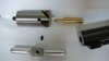
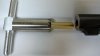
Shown is a 90-degree 1" rifle facing cutter (Brownells 080586910), brass .38 pilot (080944380), and cutter handle (080589000). The little allen screw locks the pilot inside the cutter.:

Facing cutter ready to go.:

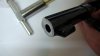
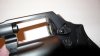
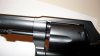
I used ATfluid in place of cutting fluid. I had to stop often and clean out the chips from the cutter, wipe off the muzzle and blow air down the bore to be sure it was clear of chips. Here's the finished cut.:

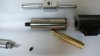
Now it's time to cut some kind of crown. Shown is the same cutter handle and brass pilot along with an 11-degree (aka 79-degree) 3/4" crowning cutter (080586750).:

.
Shown is a 90-degree 1" rifle facing cutter (Brownells 080586910), brass .38 pilot (080944380), and cutter handle (080589000). The little allen screw locks the pilot inside the cutter.:
Facing cutter ready to go.:
I used ATfluid in place of cutting fluid. I had to stop often and clean out the chips from the cutter, wipe off the muzzle and blow air down the bore to be sure it was clear of chips. Here's the finished cut.:
Now it's time to cut some kind of crown. Shown is the same cutter handle and brass pilot along with an 11-degree (aka 79-degree) 3/4" crowning cutter (080586750).:
.
Attachments
Last edited:
Sylvan-Forge
Member
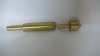
Crowning cutter all set.:

Much like cutting the face square, I had to stop often and clean out the cutter and bore. After one of the last cuts I found a slight gouge out of two of the lands about 1/4" down where a chip got caught between the pilot and bore. I should have been more patient, more thorough, and probably should have obtained a seperate pilot for this operation. Live and learn
I read somewhere about a fellow doing a crown cut and he used a progressively lighter pressure for each cutting session to obtain a smooth finish. It seemed to work out pretty well.
Here's the finished crown cut.:

After cutting I needed to remove the sharp edges and slight burring left behind. I used a 45-degree brass lap (080624045) first, followed by the rounded one (080764410). I used both with some abrasive compound. I only used this by hand, though it says to chuck it up in a drill. No edges at the transit of the bore-to-crown caught on my pinky nail, so I think it'll be good to go.:

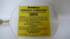
Abrasive compound, 600 grit (083045600).:

.
I've yet to put a decent radius or bevel on the outer edge of the barrel at the muzzle. Hmm.. I wonder if there is such a thing as a cupped file?
.
Much like cutting the face square, I had to stop often and clean out the cutter and bore. After one of the last cuts I found a slight gouge out of two of the lands about 1/4" down where a chip got caught between the pilot and bore. I should have been more patient, more thorough, and probably should have obtained a seperate pilot for this operation. Live and learn
I read somewhere about a fellow doing a crown cut and he used a progressively lighter pressure for each cutting session to obtain a smooth finish. It seemed to work out pretty well.
Here's the finished crown cut.:
After cutting I needed to remove the sharp edges and slight burring left behind. I used a 45-degree brass lap (080624045) first, followed by the rounded one (080764410). I used both with some abrasive compound. I only used this by hand, though it says to chuck it up in a drill. No edges at the transit of the bore-to-crown caught on my pinky nail, so I think it'll be good to go.:
Abrasive compound, 600 grit (083045600).:
.
I've yet to put a decent radius or bevel on the outer edge of the barrel at the muzzle. Hmm.. I wonder if there is such a thing as a cupped file?
.
Attachments
Last edited:
Sylvan-Forge
Member
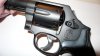
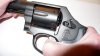
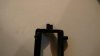
Bob Hammer
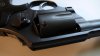
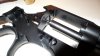
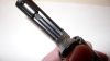
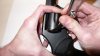
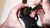
I have a new appreciation for the quality of the MIM alloy after cutting off the hammer spur. I started to try and use a hacksaw to start the cut, and I'm sure if I'd have been more patient I would have eventually obtained a good bite with the blade (same Lenox used to cut barrel), but I went with using a pneumatic cut-off tool to get an initial bite.
The surface hardness was impressive!
Back to the hacksaw for the rest of the cutting. I swear I could feel that the metal inside the hammer was utterly uniform and my blade tracked perfectly striking no voids or hardspots.
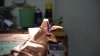
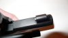
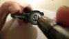
It hung on right to the bitter end with a paper thin section of metal that was still quite strong!:

About a 1/32" ridge was left at the bottom of the cut when I finally snapped the spur off. I filed on this ridge to get it flat/blended. I then blended the area near the top of the cut to the original radius. Next, I applied some Dykem Blue layout fluid to aid my eyes for final shaping/blending.:

Almost all of the shaping was done with a 6" #2 cut, swiss pattern file with safe edges, some 3M 150 grit aluminum oxide sandpaper cut into thin strips for shoeshine style sanding along with some Norton EZ-Flex 600 grit (657110600) for same. Final polishing with some Cratex medium abrasive 9/32" bullet points chucked up in the Dremel.:

.
I have a new appreciation for the quality of the MIM alloy after cutting off the hammer spur. I started to try and use a hacksaw to start the cut, and I'm sure if I'd have been more patient I would have eventually obtained a good bite with the blade (same Lenox used to cut barrel), but I went with using a pneumatic cut-off tool to get an initial bite.
The surface hardness was impressive!
Back to the hacksaw for the rest of the cutting. I swear I could feel that the metal inside the hammer was utterly uniform and my blade tracked perfectly striking no voids or hardspots.
It hung on right to the bitter end with a paper thin section of metal that was still quite strong!:
About a 1/32" ridge was left at the bottom of the cut when I finally snapped the spur off. I filed on this ridge to get it flat/blended. I then blended the area near the top of the cut to the original radius. Next, I applied some Dykem Blue layout fluid to aid my eyes for final shaping/blending.:
Almost all of the shaping was done with a 6" #2 cut, swiss pattern file with safe edges, some 3M 150 grit aluminum oxide sandpaper cut into thin strips for shoeshine style sanding along with some Norton EZ-Flex 600 grit (657110600) for same. Final polishing with some Cratex medium abrasive 9/32" bullet points chucked up in the Dremel.:
.
Attachments

Last edited:
Sylvan-Forge
Member
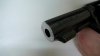
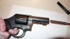
Well, I had the muzzle radiused/dehorned pretty decent, but smudged up the crown with a cratex bit. It probably wouldn't affect accuracy one bit, but I couldn't deal with that blemish (of course ), so I cleaned it up using the facing cutter and crowning cutter with only a few light turns on each. Seems pretty fair now.
Did some test firing and the first 6 went off fine, but I had 3 light strikes during the next 6 rounds due to a strain screw I had shortened too much. It was running in conjunction with a Wolff lightweight mainspring and the bobbed hammer.
I swapped the light mainspring for the factory standard weight, but still had light primer strikes. Pulled the shortened strain screw and put the standard length in and went back to the lightened mainspring = all good.
Lesson learned: There is a very narrow window for strain screw modding.
The trigger actually feels smoother, though a little heavier when using the normal strain screw over the (overly) shortened one. Maybe a couple-few thousands taken off the strain screw would be ok, but thats probably it. (Especially if using a bobbed hammer).
.
), so I cleaned it up using the facing cutter and crowning cutter with only a few light turns on each. Seems pretty fair now.Did some test firing and the first 6 went off fine, but I had 3 light strikes during the next 6 rounds due to a strain screw I had shortened too much. It was running in conjunction with a Wolff lightweight mainspring and the bobbed hammer.
I swapped the light mainspring for the factory standard weight, but still had light primer strikes. Pulled the shortened strain screw and put the standard length in and went back to the lightened mainspring = all good.
Lesson learned: There is a very narrow window for strain screw modding.
The trigger actually feels smoother, though a little heavier when using the normal strain screw over the (overly) shortened one. Maybe a couple-few thousands taken off the strain screw would be ok, but thats probably it. (Especially if using a bobbed hammer).
.
Last edited:
Sylvan-Forge
Member
After the test firing I used the rounded brass lap for a few turns to insure there were no burrs at the crown. Went loopy and blended the original yoke to the new frame, dehorned the sharp edge on the frame under the yoke and the back of the locking bolt/barrel lug. Also put a slight bevel on the back of the cylinder.
I guess its finally ready to go get blasted and blued.

.
Coming soon:
Refinishing results.
Yoke alignment, endshake & timing checks.
Fitting new cylinder bolt & extractor rod.
Fitting new cylinder stop & hand.
.
I guess its finally ready to go get blasted and blued.
.
Coming soon:
Refinishing results.
Yoke alignment, endshake & timing checks.
Fitting new cylinder bolt & extractor rod.
Fitting new cylinder stop & hand.
.
Attachments
Sylvan-Forge
Member
Sylvan-Forge
Member
Sylvan-Forge
Member
Checkout
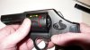
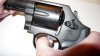
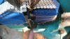
Yoke alignment (see post #33 & #34 on page 2 for detailed descript). It's good. Also, the yoke barrel flange is snug against the frame and there is no yoke endshake.:

The pivot (yellow) doesn't quite come to flush with the recoil plate. This is serviceable (though not optimal) as the end of the cylinder's center pin is radiused, but I'm going to deal with this later when I replace the cylinder bolt.:

The locking bolt looks good.:

Which leads us to a quick and dirty alignment check, say for when looking over a revolver before purchasing. Basically cycle the action with the trigger and watch to see if the space between the yoke and frame (yellow) expands or contracts. You don't have to let the hammer fall if you'd rather not, but cycle the action as far as possible. (Note: You may be able to feel the yoke deflecting down to maybe 0.0005" to 0.001", which I gather is fine, but you probably wouldn't be able to see it).:

.
Yoke alignment (see post #33 & #34 on page 2 for detailed descript). It's good. Also, the yoke barrel flange is snug against the frame and there is no yoke endshake.:
The pivot (yellow) doesn't quite come to flush with the recoil plate. This is serviceable (though not optimal) as the end of the cylinder's center pin is radiused, but I'm going to deal with this later when I replace the cylinder bolt.:
The locking bolt looks good.:
Which leads us to a quick and dirty alignment check, say for when looking over a revolver before purchasing. Basically cycle the action with the trigger and watch to see if the space between the yoke and frame (yellow) expands or contracts. You don't have to let the hammer fall if you'd rather not, but cycle the action as far as possible. (Note: You may be able to feel the yoke deflecting down to maybe 0.0005" to 0.001", which I gather is fine, but you probably wouldn't be able to see it).:
.
Attachments
Last edited:
Sylvan-Forge
Member
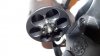
There's no detectable endshake (yellow) but it's probably still around 0.001". There is a little more rotational play (red) than before. This is something else I'll address later when fitting a new cylinder stop.:

In red you can see the hand moved up a bit in its travel since the action is partly cycled. In yellow, the top of the cylinder stop, and in green, the cylinder's stop notch. (Note: In order to cycle the action with the cylinder out, don't forget to pull back on the thumb-piece).:

The extractor/ratchet looks servicable, though there is some minor scrapes from when the charge holes were beveled.:

Checkout : Carry-up test
At rest, the cylinder stop is fully in the cylinder stop-notch.:

.
In red you can see the hand moved up a bit in its travel since the action is partly cycled. In yellow, the top of the cylinder stop, and in green, the cylinder's stop notch. (Note: In order to cycle the action with the cylinder out, don't forget to pull back on the thumb-piece).:
The extractor/ratchet looks servicable, though there is some minor scrapes from when the charge holes were beveled.:
Checkout : Carry-up test
At rest, the cylinder stop is fully in the cylinder stop-notch.:
.
Attachments
Last edited:
Sylvan-Forge
Member
Trigger squeezed very slowly.
At ~1/6 trigger travel, the cylinder stop drops below flush in the frame. A hair past 1/6th, the hand interfaces a slot on the ratchet and begins to rotate the cylinder.:

A little before 3/6 or 1/2 trigger travel you will hear a click as the cylinder stop pops into contact with the smooth portion of the cylinder.:

At ~5/6 trigger travel you should hear the second click as the cylinder stop drops into the stop notch on the cylinder. The cylinder should now be presenting the next charge hole in perfect alignment with the barrel bore.:

At last, the hammer falls. If the cylinder stop drops into the stop notch just as the hammer falls, timing will need to be adjusted. Sooner if you shoot a good bit, maybe later if not so much. At the very least the cylinder stop must drop into the notch as the hammer falls. [Mine is right at the raggedy edge on 3 of the charge holes, so I'm hoping it will be rectified by fitting a new hand and cylinder stop + a little ratchet clean-up.] Also, note firing pin protrusion, it should span the gap by a hair over half way. Make sure the firing pin retracts fully when the trigger is released.

.
At ~1/6 trigger travel, the cylinder stop drops below flush in the frame. A hair past 1/6th, the hand interfaces a slot on the ratchet and begins to rotate the cylinder.:
A little before 3/6 or 1/2 trigger travel you will hear a click as the cylinder stop pops into contact with the smooth portion of the cylinder.:
At ~5/6 trigger travel you should hear the second click as the cylinder stop drops into the stop notch on the cylinder. The cylinder should now be presenting the next charge hole in perfect alignment with the barrel bore.:
At last, the hammer falls. If the cylinder stop drops into the stop notch just as the hammer falls, timing will need to be adjusted. Sooner if you shoot a good bit, maybe later if not so much. At the very least the cylinder stop must drop into the notch as the hammer falls. [Mine is right at the raggedy edge on 3 of the charge holes, so I'm hoping it will be rectified by fitting a new hand and cylinder stop + a little ratchet clean-up.] Also, note firing pin protrusion, it should span the gap by a hair over half way. Make sure the firing pin retracts fully when the trigger is released.
.
Attachments
Last edited:
Sylvan-Forge
Member
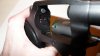
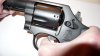
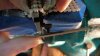
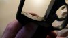
Checkout : Cylinder to bore alignment
A quick visual check can be made to detect any gross misalignment using a flashlight and an eyeball. Alternately, you can direct the light to shine in at the recoil plate as detailed in the revolver forum's checkout sticky. Check each charge hole with the trigger held back after the hammer falls. You could do this test in conjuction with the carry-up test.:

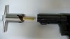
For a more accurate alignment check, I'm using a service range rod.:

Range rod head just barely visable in the b/c gap. All charge holes are in alignment with the bore.:

.
Another check made but not shown was for hammer push off.. that is, cocking the hammer back and then while it's cocked, pull back on the hammer like your trying to cock it again, then putting moderate fore and side-to-side pressure on the hammer to check that it won't slip from the sear.
.
.
A quick visual check can be made to detect any gross misalignment using a flashlight and an eyeball. Alternately, you can direct the light to shine in at the recoil plate as detailed in the revolver forum's checkout sticky. Check each charge hole with the trigger held back after the hammer falls. You could do this test in conjuction with the carry-up test.:
For a more accurate alignment check, I'm using a service range rod.:
Range rod head just barely visable in the b/c gap. All charge holes are in alignment with the bore.:
.
Another check made but not shown was for hammer push off.. that is, cocking the hammer back and then while it's cocked, pull back on the hammer like your trying to cock it again, then putting moderate fore and side-to-side pressure on the hammer to check that it won't slip from the sear.
.
.
Attachments
Last edited:
Sylvan-Forge
Member
Checkout : Headspace indication (not for recessed-head cylinders), No-Go.
Note, this is for getting a basic idea of a hazardous headspace condition or NO-GO only. To be precise, you need a real headspace gauge.
A 0.010" feeler gage must not fit betwen the firing pin bushing and an empty (and preferably deprimed) commercially available brass case.
Make sure the cylinder, extractor/ratchet, recoil plate and firing pin bushing are clean and free of any raised burrs.
Pull back evenly and firmly on the cylinder and see if you can get a 0.010" feeler gauge in from the side-plate side between the firing pin bushing and an empty brass casing. Make sure that if a casing has a fired primer in it that it is not sticking out beyond the case itself. A 0.010" should not be able to get in there. (According to JK, this is debated to 0.012").
In the pic, I can't get my 0.010" feeler straight in because it is too wide, so I had to go in at an angle in order to clear the extractor/ratchet and the top-strap. This only gives one corner of useable feeler gauge. It would go behind the case that's next in line to be fired, but not the case in front of the firing pin, so it's good.:

I tried the 0.012" and it wouldn't go behind any case on the sideplate side.:

.
Every charge hole position should be checked.
.
Notes:
I used Starline cases with a rim thickness of 0.058"
0.058 + 0.010 = 0.068
Please see page 2 for gauging with Brownells 080-633-668 Cylinder Gauge.
And it was not mentioned, but the cylinder should also be pulled back evenly and firmly when using the Brownells tool, even though the instructions omit this.
.
Note, this is for getting a basic idea of a hazardous headspace condition or NO-GO only. To be precise, you need a real headspace gauge.
A 0.010" feeler gage must not fit betwen the firing pin bushing and an empty (and preferably deprimed) commercially available brass case.
Make sure the cylinder, extractor/ratchet, recoil plate and firing pin bushing are clean and free of any raised burrs.
Pull back evenly and firmly on the cylinder and see if you can get a 0.010" feeler gauge in from the side-plate side between the firing pin bushing and an empty brass casing. Make sure that if a casing has a fired primer in it that it is not sticking out beyond the case itself. A 0.010" should not be able to get in there. (According to JK, this is debated to 0.012").
In the pic, I can't get my 0.010" feeler straight in because it is too wide, so I had to go in at an angle in order to clear the extractor/ratchet and the top-strap. This only gives one corner of useable feeler gauge. It would go behind the case that's next in line to be fired, but not the case in front of the firing pin, so it's good.:
I tried the 0.012" and it wouldn't go behind any case on the sideplate side.:
.
Every charge hole position should be checked.
.
Notes:
I used Starline cases with a rim thickness of 0.058"
0.058 + 0.010 = 0.068
Please see page 2 for gauging with Brownells 080-633-668 Cylinder Gauge.
And it was not mentioned, but the cylinder should also be pulled back evenly and firmly when using the Brownells tool, even though the instructions omit this.
.
Attachments
Last edited:
tractorshaft
member
Fantastic work, thanks for taking the time and doing it right. I know the effort required to do this. Hundreds will benefit from the "Visual Aids" you have provided. Best regards
Sylvan-Forge
Member
tractorshaft, thank you for the kind words and you are most welcome.
.
.
Sylvan-Forge
Member
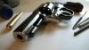
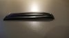
Here's a picture showing 3 mainsprings (aka hammer springs). In the fore is the factory (OE) spring, note how flat it is. In the middle is the Wolff TYPE-1 Power Rib Mainspring showing a little more bend or arch (same pull weight as OE, though it does seem smoother), and in the back is the Wolff TYPE-2 Power Rib Mainspring with the most arch and the lightest pull weight.:

.
.
Attachments
Last edited:
Sylvan-Forge
Member
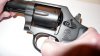
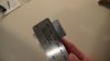
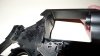
Bolt Fitting
Here's the new bolt.:

New bolt on the left, old on the right. The new bolt's pivot only needs to be filed so that it's just a hair longer than the old one. This is the only "fitting" that needs to be done aside from checking it for straightness.:

Steel rule and aluminum block for a makeshift filing jig.:

.
Here's the new bolt.:
New bolt on the left, old on the right. The new bolt's pivot only needs to be filed so that it's just a hair longer than the old one. This is the only "fitting" that needs to be done aside from checking it for straightness.:
Steel rule and aluminum block for a makeshift filing jig.:
.
Attachments
Last edited:
Sylvan-Forge
Member
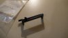
Top-down view of the bolt set atop the ruler and clamped against the block. The bench-vise jaws are only bearing on the ruler and alum. block.:

Really just using this setup as a visual guide (file not touching the ruler) and to give my hands a break.:

Pivot above flush. Just a little more to go. Even with using my jig, it isn't perfectly squared to the recoil plate. I'll use a magic marker to indicate any high spots needing additional file-love.:

I didn't use the jig for the final filing and deburring. Polished smooth with a medium cratex in the dremel. The pivot is maybe 0.001" longer than the old one, and sets just below flush, but it does function better. I had tested it when it was perfectly flush and it seems that any slight lateral movement (say bumping the thumbpiece) of the bolt when closing the cylinder can cause the pivot to stick out just enough to catch/bind against the extractor.:

.
Really just using this setup as a visual guide (file not touching the ruler) and to give my hands a break.:
Pivot above flush. Just a little more to go. Even with using my jig, it isn't perfectly squared to the recoil plate. I'll use a magic marker to indicate any high spots needing additional file-love.:
I didn't use the jig for the final filing and deburring. Polished smooth with a medium cratex in the dremel. The pivot is maybe 0.001" longer than the old one, and sets just below flush, but it does function better. I had tested it when it was perfectly flush and it seems that any slight lateral movement (say bumping the thumbpiece) of the bolt when closing the cylinder can cause the pivot to stick out just enough to catch/bind against the extractor.:
.
Attachments
Last edited:
Sylvan-Forge
Member
PLEASE NOTE! CORRECTION to Checkout : Carry-up test
On newer revolvers that do not utilize pins to locate the extractor on the cylinder you must use properly sized [and empty] cases in order to obtain a correct indication on the carry-up test posted.
.
On newer revolvers that do not utilize pins to locate the extractor on the cylinder you must use properly sized [and empty
] cases in order to obtain a correct indication on the carry-up test posted..
Brian Dale
Member
Great heavens; what a marvelous piece. You've put in a terrific amount of meticulous effort, and you've succeeded in creating an outstanding reference work for us all to use. Thank you.
Thanks Sylvan-Forge,
Really excellent Thread...
I don't know how I'd missed till now, but glad I found it.
As it happens, I am similarly preparing to modify in his case, an older Model 10-6, and your info is much appreciated.
Would you know if there are Barrel-end Cutters available for duplicating the normal original S & W 'roundness' of the Muzzle end, after one has shortened a Bull Barrel?
Or, does one have to make their own Piloted Cutter to do so? ( I expect one could re-profile any large enough conventional Machinist's Counter-Bore for doing it...)
Phil
l v
- Status
-
Not open for further replies.
Similar threads
- Replies
- 2
- Views
- 519
- Replies
- 13
- Views
- 915
- Replies
- 8
- Views
- 1K
- Replies
- 10
- Views
- 822
- Replies
- 10
- Views
- 2K