No insult intended, but the engineers at S&W have a little bit more experience with this than you, and the fewest moving parts did not turnout to be the 'best' design.
Anyway, this is one my favorite subjects.
It has long been known that a strong impact to the hammer of a revolver could result in an accidental discharge if the hammer was down on a loaded chamber.
'In the beginning' percussion single action revolvers only had two hammer positions. Half cock, which was the position that allows the cylinder to rotate for loading, and full cock. And of course when the gun fired, the hammer went all the way down. There was no 'safety cock' position on single action Cap & Ball revolvers. In other words, there was no cocking notch that allowed the hammer to be pulled back just a little way from the chamber, or nipple as the case may be. Some early Colts had twelve (not six) locking slots on the cylinder so the cylinder could be locked in place without a nipple being exposed to the hammer. The twelve slot idea went away pretty quickly, probably more expensive to produce than just six slots. But most percussion revolvers had an alternate method of keeping the hammer down between chambers with all the chambers loaded.
This is a cartridge conversion cylinder for a Remington Model 1858. So it is not really a Cap & Ball cylinder. On this cylinder, six independent firing pins take the place of the nipples on a C&B revolver. But notice the notches cut into the cylinder cap between each firing pin. The idea is, to safely load six rounds into this cylinder, the hammer nose would be let down into a slot between the firing pins, locking the cylinder in place until the hammer was cocked to fire the revolver. (I never load this cylinder with six rounds, but that is a different story.)
View attachment 843070
Colts had little pins set between the chambers, and a hollow in the hammer that would fit over the pins. The cylinder on the left is a Pieta 1860 Army cylinder. You get the idea.
View attachment 843071
By the time Colt introduced the Single Action Army cartridge revolver in 1873 a 'safety cock' notch had been added to the hammer. This is the lockwork of a Colt Single Action Army. The upper arrow is pointing to the 'safety cock' notch on the hammer. The lower arrow is pointing to the sear, which is the tip of the hammer that fits into the different cocking notches on the hammer. So in theory it was safe to load a Colt with six rounds, and ease the hammer back to the safety position. In fact, it was soon discovered this was not safe. Notice how thin the sear is. It would not take much of a blow to the hammer to shear off the tip of the sear, allowing the hammer to fall all the way. If the blow to the hammer was strong enough, like for instance the gun was dropped and landed on the hammer spur on a hard surface, there was a very good chance the revolver would discharge. So anyone familiar with a Colt style lockwork never loads all six, the hammer is always let down on an empty chamber. Of course John Wayne once said 'if you think you need six, then load all six'. But what did he know, he was an actor. Anyway, most single action cartridge revolvers made in the second half of the 19th Century, had a similar 'safety cock' notch built into the hammer. By the way, I always refer to the 'safety cock' notch in quotes, because it is really not very safe.
View attachment 843072
Fast forward to the 1950s and Bill Ruger introduced his first single action revolvers. Ruger updated the design, replacing all the leaf type springs of the Colt with coil springs, and added a frame mounted firing pin. But the action still had the 'safety cock' notch on the hammer. These revolvers are known as the Three Screw Rugers because like a Colt, there were three frame screws for the moving parts to pivot on.
View attachment 843073
Here is the hammer and pawl (hand) of that revolver. You can see there are three cocking notches on the hammer.
View attachment 843074
And no transfer bar. The hammer smacks the firing pin directly.
View attachment 843075
During the late 1960s and early 1970s, Ruger lost some expensive lawsuits.These lawsuits resulted from injuries (and at least one death). Not being too judgemental, but the litigants obviously had not learned to only load five beans into the cylinder.So in the early 1970s Ruger completely redesigned all their revolvers to include a transfer bar. This photo shows the hammer of a Vaquero at full cock. The transfer bar has risen and is in position to 'transfer' the energy of the falling hammer to the frame mounted firing pin.
View attachment 843076
Now let's talk for a moment about less parts being the better design. Here are all the parts inside a modern Ruger, this one happens to be a New Model Vaquero. There are a lot more parts inside a modern Ruger than in the old Colt design. There are even more parts than in the Ruger Three Screw design. This is how many moving parts it takes for the mechanism to work. The part hooked onto the trigger is the transfer bar. When the trigger spring pushes the trigger all the way forward, the trigger pulls the transfer bar down, moving it from between the hammer and the firing pin, so no matter how hard the hammer may be struck, it will not contact the firing pin. When the hammer is cocked, it physically rocks the trigger back, which in turn pushes the transfer bar up, positioning it between the hammer and the firing pin. And yes, since the motion of the trigger is what controls the position of the transfer bar, the tiny amount of trigger motion required to release the hammer from full cock does result in the transfer bar rising a little bit further. It does not really matter, the transfer bar never covers more than about half the firing pin anyway.
View attachment 843077
By the way, here is a patent drawing assigned to Iver Johnson for the first transfer bar. Notice the date.
View attachment 843078
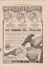
Iver Johnson put so much faith in their transfer bar design they had an advertising campaign titled 'Hammer the Hammer'.
View attachment 843079
Before I move on from Rugers, here is a photo of the transfer bar in the only double action Ruger I own, a GP 100. This is an older one, it was made in 1997. I'll bet the new ones are not much different. The hammer is at full cock, of course there are only two potions, full cock and all the way down. The transfer bar has risen to the 'firing position' so it can transfer the hammer blow to the frame mounted firing pin.
View attachment 843080
----------------------------------
Double Action Revolvers.
With double action revolvers it became apparent that the hammer had to be withdrawn a bit to open the gun for loading and unloading. This was even true with the double action Top Break revolvers. This is the lockwork of a S&W Double Action 44 Top Break revolver. In this photo the hammer is all the way down, and the firing pin is protruding through the frame.
View attachment 843081
In this view, the hammer has been eased back to the 'safety cock' posiiton, pulling the firing pin back so it will not get stuck in a fired primer under the hammer. Notice the 'safety cock' notch has been engaged by the rear sear underneath the hammer. Generally speaking, with Top Breaks like this, this hammer position was called Half Cock, even though the hammer did not really go halfway back.
View attachment 843082
Just for fun, here is the hammer at the full cock position.
View attachment 843083
When double action revolvers with side swinging cylinders were designed, it became standard for the hammers to aromatically retract, so the firing pin would retract and not get hung up in the dent of a fired primer.
This is the lockwork of a S&W Model 1899 Military and Police revolver. The part the arrow is pointing to is called the Rebound Lever. The spring at the rear of the Rebound Lever is pushing the hump at the top of the lever against the hammer, wedging the hammer back from the frame slightly. Notice there is a slight space between the front of the hammer and the frame. If the cylinder was open, we would see the firing pin had been withdrawn and the cylinder could be opened without any jamming of the firing pin in a spent primer. This is the normal 'at rest' position of the hammer.
View attachment 843084
In this photo I am keeping the trigger back, as if I had just fired the revolver. The trigger has forced the front of the Rebound Lever down. This allows the hammer to fall all the way. Notice the gap between the hammer and the frame has closed, allowing the firing pin to protrude through the frame and fire a round.
View attachment 843085
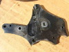
By 1905 S&W had redesigned the lockwork of their Hand Ejector revolvers. The Rebound Lever was replaced by the Rebound Slide. In this photo the Rebound Slide is the part under the hammer with the patent date on it. This is basically the same way S&W revolvers are made today. The Rebound Slide has a strong coil spring inside that pushes the Slide forward. When the revolver is in the 'at rest' position, the spring shoves the Rebound Slide forward so the hump on top wedges the hammer back. This is the normal position of the lockwork, the hammer is back, not contacting the frame, and the firing pin is withdrawn so the cylinder can be swung open for loading and unloading. At this time, there was no Hammer Block inside S&W revolvers. The only 'safety mechanism' was the rebound slide, forcing the hammer back. In theory it was safe to fully load these revolvers and leave the hammer 'down' on an empty chamber. However a really strong blow to the hammer could shear off the bottom of the hammer where I have drawn a red line, allowing the hammer to fall all the way and possibly discharge the firearm. I have no direct experience with this, but I strongly believe this system was still safer than the old Colt design. I suspect it would take a much heavier blow to this hammer to break something than it would with the old Colt Single Action Army design, just because of the thickness of the cross sections of the parts.
View attachment 843086
As a remedy to the weakness of the rebounding hammer, this is the first style of Hammer Block that S&W designed for their double action revolvers very early in the 20th Century. A slot was cut into the side plate and a hammer block made of spring steel was peened into place. In the normal position, the tab at the top of the hammer block positioned itself between the hammer and the frame, so the hammer could not fall all the way. A ramp on the pawl pushed a spring loaded pin sideways as the hammer moved rearward, withdrawing the hammer block into the side plate, allowing the hammer to fall all the way.
View attachment 843087
I'm not sure exactly when this second style of Hammer Block replaced the first style, probably in the 1920s. This time the design was simplified, probably to save cost. The Hammer Block was still a piece of spring steel peened into the side plate. The spring loaded pin was gone. Now there was a tab on the side of the Hammer Block that was engaged by a ramp on the pawl. As the hammer moved back, and the trigger moved back, the ramp on the pawl shoved the hammer block into the side plate, allowing the hammer to fall all the way.
This is the style of Hammer Block involved in the incident in 1944 when a S&W Victory Model fell to the deck of a warship and discharged, killing a sailor. I have no information about whose revolver it was, nor how far it fell. The inquiry into the event found that cosmoline inside the gun had probably hardened, causing the hammer block to be withdrawn in its slot, overcoming the spring action of the hammer block. So when the revolver fell on its hammer, and the lower part of the hammer broke, or perhaps the Rebound Slide was crushed, there was nothing preventing the hammer from riding forward and discharging the revolver.
View attachment 843088
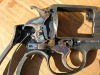
The Army ordered Smith and Wesson to get to the bottom of the problem pronto. S&W had a large contract to provide revolvers to the Army, and the Army threatened to cancel the contract. Smith and Wesson conducted tests, dropping revolvers onto the hammer spur, and there were enough failures to warrant a redesign. The engineers were called in and within a week the new Hammer Block design was ready. The new Hammer block was a separate piece of stamped steel, riding in a slot in the side plate. A pin on the Rebound Slide pulled the Hammer Block down when the hammer and the trigger rotated back, allowing the hammer to fall all the way. When the trigger was released, the pin shoved the hammer block up in its slot, blocking the hammer from falling all the way. This style of hammer block is still incorporated in Smith and Wesson revolvers today. As with all three of the Hammer Block designs, it is a redundant safety device, only coming into play if the Rebound Slide no longer wedges the hammer back. Notice the hump on top of the Rebound slide is doing its job of keeping the hammer back. There is a small amount of space and the Hammer Block is actually not doing anything. If the parts holding the hammer back should fail, then the Hammer Block will come into play.
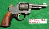
Interestingly enough, Victory Models issued before the new Hammer Block design had a V (for Victory) prefix on the Serial Number. After incorporation of the new Hammer Block design they had a SV prefix.
View attachment 843089

")