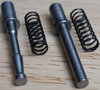
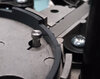
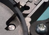
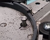
Problem: Priming chute/trough pin does not contact the frame column groove rings enough to shake the primer tray
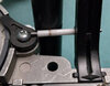
Solution: Rotate the top carrier cover counter-clockwise when tightening the two flathead metal screws while ensuring the priming rod/pin moves up and down freely.
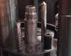
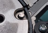
When the two top carrier cover flathead screws are tightened, if no attention is given to where the pin is in relation to the frame column/groove ring, then top cover will be tightened with pin not contacting the frame column/groove rings.
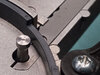
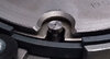
To prevent this, when you tighten the two top carrier cover flathead screws (while holding the bottom cover with your hand), see if you can place the primer chute/trough pin in the lower groove ring by torquing the cover counter-clockwise before tightening to put more pressure on the pin (But ensure the priming pin moves up and down freely).
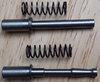
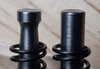
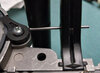
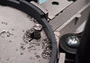
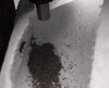
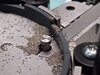
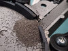
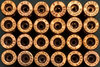
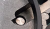
With the pin closer to the frame column/groove rings, adding the DIY pen filler sleeve roller mod will help shake the primer tray better (Also, if you have additional trays, try others and use the one that moves the primers to chute/trough opening the best).
When I torqued the top carrier cover too much, I noticed binding of priming rod/pin to not move up and down freely (because bottom cover is held captive by the ram), so I backed off the torquing of top carrier cover but that resulted in the pin not contacting the bottom groove ring (pin contacted the top groove ring fine to shake the primer tray). With the DIY pen filler sleeve roller mod for the pin, it now contacts the lower groove ring as well and contacts the upper groove ring to shake the primer tray more.
When John Lee redesigned the priming rod/pin, he may not have realized that reshaped rod/pin could be addressing another issue of primer tray not shaking enough due to pin not contacting the groove rings and I will be testing that when the new priming pin arrives. Stay tuned.
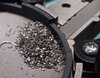
When I have been tightening the two flathead metal screws I have been watching to make sure the locator pin was centered in the hole on the carrier cover. I have not been watching the pin for the primer tray. Which is more critical? They both are. If the locator pin is not centered it can drag when the carrier goes up and down, and if the primer tray doesn't get shaken the primers will not feed consistently. Will take a look, but I think Lee may need to take a look at the lack of the primer tray being shaken enough. I did try another tray and found that one of the new trays I received with the press was pressed together in the middle and was restricting primer flow. The one I am using now is one I have used for quite some time on my Load-Master without any problems. The Load-Master gives the trays a good shake with the raised bumps on the side, the Six Pack Pro not as much. This is one area that may take a little more "fine tuning".