OP
OP
LiveLife
Member
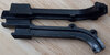
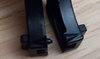
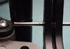
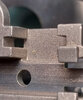
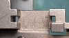
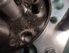
Added bottom carrier cover picture to "Redesigned 'self cleaning' priming pin stress test" under "Troubleshooting and Solutions".
NOTE: Please keep in mind that product operation and update parts information of this newly launched press is dynamic and changing with pre/early production parts; therefore, presses with different mix of production run parts may exist. While I attempt to stay current and be accurate as possible, do realize that information posted on this thread are based on my personal experience with my personal press and parts that have been clarified with contact with Lee Precision. Parts design/update/production runs/lots can vary and influence how they perform in your press.
Press Set Up:
- WARNING: DO NOT remove carrier core from the ram as 80 ft/lbs is required to secure the core to the ram with very precise alignment. Instead, follow this Lee Precision video on removing carrier core and ram as a single unit.
- Press mounting and initial set up (Bench mounting and drill template)
- Press lubrication
- SPP size comparison to Dillon 550
- SPP size comparison to ABLP
- Selecting powder charge station to prevent powder entering priming rod/pin sleeve (Issue addressed with redesigned rod/pin)
- Initial set up of dies (Lee Precision instructions)
- Setting up dies for greater precision
- Inline bullet feeder/rotary magazine and stepped "M" style powder through expander R&D
- Powder measure with Bottle Adapter using factory powder container
- Part 1 - New priming system overview and primer seating depth
- Part 2 - New priming system detail and small/large primer guide removal
- Part 1 - Priming system using same priming rod/pin for small/large primers
- Part 2 - Priming system using same priming rod/pin for small/large primers
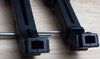
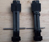
- Part 1 - Updated priming rod/pin with no charge replacement (Resolved sticky pin, pin stuck in primer pocket and powder in sleeve issues)
- Part 2 - Redesigned "self-cleaning" priming pin overview
- Part 3 - Redesigned "self-cleaning" priming pin stress test
- Part 4 - Redesigned "self-cleaning" priming pin dry priming test
- Press disassembly and reassembly step-by-step (Lee Precision instructions)
- SPP ram, linkage and lever are same as .50 caliber Classic Cast single stage press
- Linkage reassembly instructions
- Shellplate detent ball and spring
- Part 1 - Enhanced top and bottom carrier cover reassembly
- Part 2 - Enhanced top and bottom carrier cover reassembly with redesigned priming pin (Even greater primer chute/trough pin contact with groove rings)
- Inherent progressive press shellplate tilt/deflection affecting OAL variance (Lee Precision explanation)
- OAL variance testing with mixed/sorted range brass by headstamp in progressive mode
- OAL variance listing by headstamp in progressive mode
- OAL consistency testing methodology
- Part 1 - OAL consistency enhancement when using mixed range brass
- Part 2 - OAL consistency enhancement when using mixed range brass
- Primer slider spring crushing/end snagging primer slider channel tabs (Updated with longer slider and narrower spring end)
- Priming rod/pin not actuating freely (Resolved with redesigned rod/pin)
- Shellplate to top press head/die alignment (DIY alignment with shellplate full of cases before tightening three hex bolts)
- Powder entering priming rod/pin sleeve (Resolved with redesigned rod/pin)
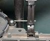
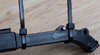
- Primer chute/trough pin not contacting the groove ring to shake the tray (DIY sleeve roller for pin - DIY stress test)
- Roller handle R&D issue
- Case feeding is not smooth and/or ejects cases (DIY tightening of shellplate to index shaft)
- Shellplate works itself loose to affect indexing or locks up shellplate (DIY tightening of shellplate to index shaft)
- Priming pin gets stuck in primer pocket (Resolved with redesigned pin)
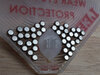
- Redesigned "self cleaning" priming pin stress test with powder poured in station #2
- Primer chute/trough pin not contacting frame column groove rings (DIY: Addresses primer tray not shaking enough)
- Enhanced Primer chute/trough pin not contacting frame column groove rings (DIY: Better address primer tray not shaking enough)
- Primers get stuck in the tray and won't slide down with press cycling (DIY mod pending)
- Longer gray primer slider with narrower spring end (Eliminates the black primer slider channel/trough retainer piece)
- Gray case retainer ring (No issue with black ring, just latest production run)
- Updated priming rod/pin with no charge replacement (Resolved sticky pin, pin stuck in primer pocket and powder in sleeve issues)
Attachments
Last edited:
")